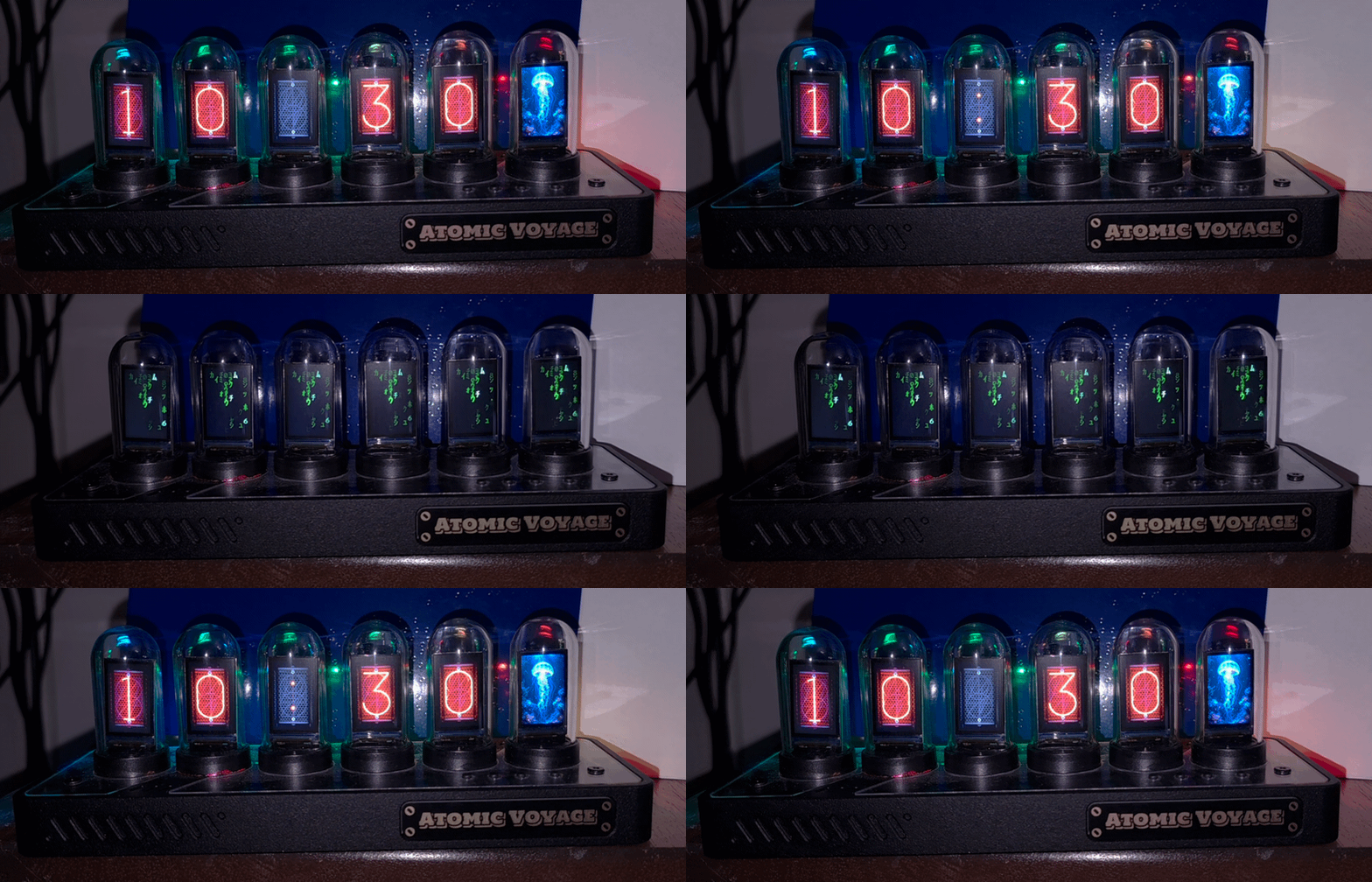
Someone gifted me an Atomic Voyage EleksTube IPS GEN3 Pro v4.3.3, a polished six-screen clock, but at first glance I did not like the heavy network-centric firmware. To use all its features, the device requires users to connect it to their home network (a potential security risk to be examined in another post), and without an active internet connection, users are limited to using the stand-alone clock with the built-in clock faces and the matrix screensaver bundled with the device. The USB-C connection powered the clock and exposed a USB-to-UART bridge, but the stock firmware did not provide a supported local control protocol.
Taking Control Without Breaking the Clock
The EleksTube IPS GEN3 Pro is sold as a decorative clock. It looks like a six-tube Nixie clock, but each "tube" contains a small IPS display. The hardware can render arbitrary pixels, store image assets, run animations, keep time through power cycles, communicate over serial, and connect to Wi-Fi or Bluetooth.
The product still behaves like a clock because that is what its manufacturer firmware decided it should be. I did not want to replace that identity. I wanted the clock to remain reliable when no computer was connected, preserve its physical controls, and continue showing time from its onboard real-time clock. I also wanted direct control over USB and the ability to repurpose the far-right display for indicators and animations.
That required taking ownership of the firmware without throwing away features from the manufacturer's design.
The Consumer Product
My unit identifies as an EleksMaker IPS GEN3 Pro, also sold as the Atomic Voyage Pro. Its stock package reported:
ELEKSMAKER-IPS-GEN3-Pro-v4.3.3-v26.0513.0001Inside is a capable embedded platform:
| Component | Verified hardware |
|---|---|
| Processor | ESP32-PICO-D4, revision 1.1 |
| CPU | Dual-core Xtensa LX6, up to 240 MHz |
| Storage | 4 MiB flash |
| External PSRAM | None |
| Displays | Six 135 × 240 IPS/TFT panels |
| Persistent clock | DS3231-compatible RTC over I2C |
| Host connection | USB-to-UART bridge |
| Radios | 2.4 GHz Wi-Fi, Bluetooth 4.2, and Bluetooth LE |
The ESP32-PICO-D4 integrates a surprising amount into one package. The clock does not need another controller to become programmable. It already has a dual-core processor, flash, multiple serial interfaces, and radio hardware.
In the stock four-digit layout, four panels render HH:MM, one renders the blinking separator, and the far-right panel is reserved for weather. The clock also includes selectable faces, RGB lighting, physical buttons, a slideshow mode, and a digital-rain Matrix animation.
As a consumer product, it was already good. My problem was not that the clock failed at being a clock. My problem was that its control model was too narrow for the hardware underneath it.
What I Wanted Instead
I had three requirements:
- The clock should not need to join my home network.
- A host should be able to control it through the USB cable already attached to it.
- If the host disappears, the device should continue operating as a normal clock.
The far-right weather display was the obvious extension point. I did not need embedded weather, and I did not want to spend one of six displays on a feature I rarely used. That panel was more useful as a small status surface for:
- event indicators
- temporary alerts
- seasonal artwork
- animated state
- future home-automation feedback
The keyword is temporary. An alert should take over the appropriate display, remain visible for a defined duration, and then return to the clock. The firmware should own that return path. A disconnected host should never leave the device stranded in a broken intermediate state.
This was less about adding one animation and more about changing who controlled the product.
A Firmware Backup Is Not Source Code
The first practical distinction was between recovery and development.
I made a complete 4 MiB backup of the manufacturer firmware and verified that it matched the device flash. That gave me a recovery path, but it did not give me maintainable source code. A binary image can be restored. It cannot be treated like an Arduino or PlatformIO project that can be opened, understood, and safely extended.
The stock USB connection also did not expose the control surface I wanted. I could observe limited serial behavior and interact with the clock's expected configuration flow, but there was no stable, documented, line-oriented USB protocol for treating the clock as a local display endpoint.
The network path was not a good substitute. Connecting a computer directly to the clock's access point meant leaving the normal network. Joining the clock to my home Wi-Fi added a radio and credential dependency to a device that sat within USB-cable distance of its host.
I wanted local control, not another small appliance waiting for a cloud-shaped reason to exist.
The Open-Source Options
There is real community work around EleksTube clocks, but "EleksTube" covers multiple generations, board layouts, clones, flash sizes, and display mappings. Firmware that works on one model can produce blank screens or worse on another.
The projects I evaluated also had different product goals:
Manufacturer firmware
Strength: Exact behavior for the shipped device.
Why it was not the final answer: The available firmware was a binary recovery image, not editable source code.
EleksTubeIPSHack
Strength: Open alternative firmware with media management and a browser-based menu.
Why it was not the final answer: It creates its own Wi-Fi access point and centers the experience around a browser and NTP.
EleksTubeHAX
Strength: Broad aftermarket support for EleksTube clocks and several compatible clones.
Why it was not the final answer: Its hardware scope and design choices differ from my specific GEN3 Pro target.
judge2005/EleksTubeIPS
Strength: Mature display, RTC, button, asset, weather, slideshow, and Matrix-animation support, including explicit V2 build targets.
Why it became the baseline rather than the final product: It was the closest hardware match, but its architecture still assumed Wi-Fi, web configuration, NTP, MQTT, and network-delivered weather. That made it the strongest foundation to build upon, not the finished system I wanted.
None of these projects were wrong. They were solving different problems.
The judge2005/EleksTubeIPS project was the only baseline I found that matched my device closely enough to preserve the proven hardware layer. Its release line already supported EleksTube V1 and V2 devices, handled all six displays, managed assets through LittleFS, supported the RTC and buttons, and included the weather, slideshow, lighting, and Matrix renderers.
That made it the right foundation.
It did not make it the final product.
Using Open Source as a Hardware Compatibility Layer
I based my fork on judge2005/EleksTubeIPS v1.9.5 at commit 9bb674d. The most valuable code was not the weather client or web interface. It was the code that knew how this physical clock worked:
- Display initialization and chip selection
- SPI coordination across six panels
- Clock-face extraction and image rendering
- RGB and backlight control
- Physical-button behavior
- RTC access
- Persisted settings
- Four-digit and six-digit layouts
- The Matrix animation
Rewriting those pieces from scratch would have been more work for little reward. So my fork treats that work as the device compatibility layer. I retained the working renderer and board behavior, then replaced the usability assumptions built above it.
That is what "rolling my own" means in this project. I did not start with a blank main.cpp. I started at the boundary where hardware enablement ended, and product policy began.
Replacing the Control Plane
The first major change was a USB serial control plane.
The USB cable appears to the ESP32 as a conventional UART stream. The host sends one ASCII command per line at 115200 baud. Requests start with @, and replies start with either @ok or @err.
A session looks like this:
@ping
@ok pong 1.9.5-usb-only.5

@get network
@ok network=disabled

@get time
@ok time=2026-07-26T18:00:38-0400

@set time_zone:EST5EDT,M3.2.0,M11.1.0
@ok time_zone="EST5EDT,M3.2.0,M11.1.0"

@set status_pane:jellyfish_stress
@ok status_pane={"preset":"jellyfish_stress","type":"gif","frames":0,"frame_ms":0}
The protocol deliberately reuses the clock's existing configuration model. A USB command does not write to a second set of shadow settings. It updates the same state used by the display and physical controls.
The implementation is split by responsibility:
- Serial command dispatcher: Buffers incoming lines, validates input, dispatches commands, and emits deterministic replies.
- Clock configuration: Preserves persisted display, brightness, clock-face, power, and mode settings.
- Offline time service: Applies POSIX timezone and daylight-saving rules without relying on SNTP.
- RTC synchronization: Stores UTC in the DS3231 and restores accurate time after a reset or host disconnection.
- Status pane: Owns the far-right display without blocking the primary clock renderer.
- LittleFS: Stores clock faces, slideshow assets, BMP indicators, and GIF files.
This separation matters because USB is only the transport. The clock still owns its state.
Removing the Network Dependency
The upstream firmware is intentionally network-centric. It uses Wi-Fi for configuration, NTP for time, weather APIs for forecasts, and MQTT for external control.
My supported target, elekstubev2_usb_only, removes those application paths.
The Wi-Fi manager, web server, MQTT startup, network weather client, and SNTP implementation are excluded from the linked application. The firmware also stops and deinitializes the ESP32 radios during startup. Network commands return:
@err network-disabledThe hardware still contains Wi-Fi and Bluetooth. Disabling them is a customization/security decision, not a physical limitation. That distinction leaves room for a future target that uses a radio intentionally. It prevents a future feature from quietly weakening the current offline boundary.
Keeping the Clock Working
Taking control of the device would have been easy if I were willing to turn it into a six-screen demo board.
I was not.
The default state remains the clock. Time survives resets through the onboard RTC. The configured POSIX timezone converts stored UTC into local time and handles daylight-saving changes. The USB host can disappear without taking the clock with it.
The existing physical behavior also remains useful:
- Button B cycles clock, date, slideshow, then back to clock
- Button D explicitly starts the Matrix animation
- Button A dismisses Matrix and returns to the clock
- Long-pressing Button B opens the clock-face menu
- Returning to clock mode now also restores the default right-most display animation
In my version, the automatic screensaver is disabled. The Matrix effect is still available, but it only appears when selected. My logic for this change was that a decorative effect should not unexpectedly replace the device's primary clock function.
Turning the Weather Panel Into a Status Pane
The upstream four-digit-with-weather layout already created the right display boundary. I replaced the weather renderer on the final panel with a dedicated StatusPane.
The status pane contains implemented paths for:
- a built-in blank state
- full-panel static BMP images
- nonblocking numbered BMP frame sequences
- native animated GIF files
Static images were straightforward. GIFs exposed the real hardware constraints.
The ESP32-PICO-D4 in this clock has no PSRAM, so allocating a large full-frame animation buffer would be a poor design. I pinned bitbank2/AnimatedGIF at version 2.2.0 and decode one scanline at a time directly to the selected TFT.
The clock can now render a 135 × 240, 256-color GIF while its time display continues advancing. A 580,244-byte, full-panel Jellyfish animation with 20 ms frame timing ran continuously with correct color and no clock corruption.
The Practical GIF Limit Is Visual
Native GIF playback worked, and the Jellyfish stress animation proved that the clock could decode a large, full-panel, high-frame-rate GIF without flashing, corrupting the image, or interrupting the clock.
Technical compatibility did not guarantee a good visual result, however. The far-right display is only 135 × 240 pixels, making fine photographic motion and small moving elements difficult to appreciate. Simpler animations with one focal object, strong contrast, limited motion, and a seamless loop looked substantially better.
Some apparent playback issues also came from the source files themselves. Long final-frame delays could resemble decoder lag, while incompatible first and last frames made otherwise functional animations appear to stutter when looping.
The practical production guidance is therefore:
- Keep the canvas at or below 135 × 240 pixels
- Prefer bold shapes over photographic detail
- Use a small number of meaningful moving elements
- Make the first and last frames visually compatible
- Keep frame delays deliberate and consistent
- Use transparency conservatively
Taking control of the display meant defining suitable media constraints, not merely adding a decoder. The hardware limit and the usability limit are not the same.
What the Device Does Now
The current firmware still behaves like a clock, but the feature boundary has changed:
- time and timezone can be supplied over USB
- the RTC keeps time without the host
- networking is disabled
- the normal default is clock mode
- Matrix is manually selected vs. as an auto-screen saver
- Gingerbread and Christmas clock faces are bundled by default for seasonal use
- the Christmas face includes a matching animated ornament colon
- the far-right screen is a programmable status pane
- native GIF assets render without stopping the clock
- physical mode transitions return to the working clock state
The source will be available in my elekstube-usb-serial repository (private at the moment but will be released in the future).
What Comes Next
The status pane creates a clean boundary for event-driven behavior.
A host can eventually send an alert with:
- a preset or animation
- a duration
- an optional temporary display mode
- priority and replacement rules
- an explicit return state
The ESP32 does not need to know how a calendar, build pipeline, home sensor, or third-party API works. Those integrations belong on the host. The clock needs a deterministic command, a local asset, and a safe way back to time.
Weather can return later as one possible host-supplied event. It no longer needs to be a permanent embedded dependency that requires internet connectivity.
This is a better division of responsibility. The host handles changing external systems. The clock handles time, state, pixels, and recovery.
Taking Ownership Without Erasing the Foundation
The most important part of this project was not making an ESP32 draw a GIF.
It was identifying the correct software boundaries and hardware limits.
The manufacturer firmware proved what the consumer product could do. The open-source community firmware provided the working hardware layer the manufacturer did not publish. My fork kept that foundation, replaced the control plane, removed network assumptions, and created a product that fits a different use case.
The result is still a clock.
It just no longer belongs entirely to the firmware it shipped with.
Sources: